 Tiếng Việt
 English
 日本語
日本語
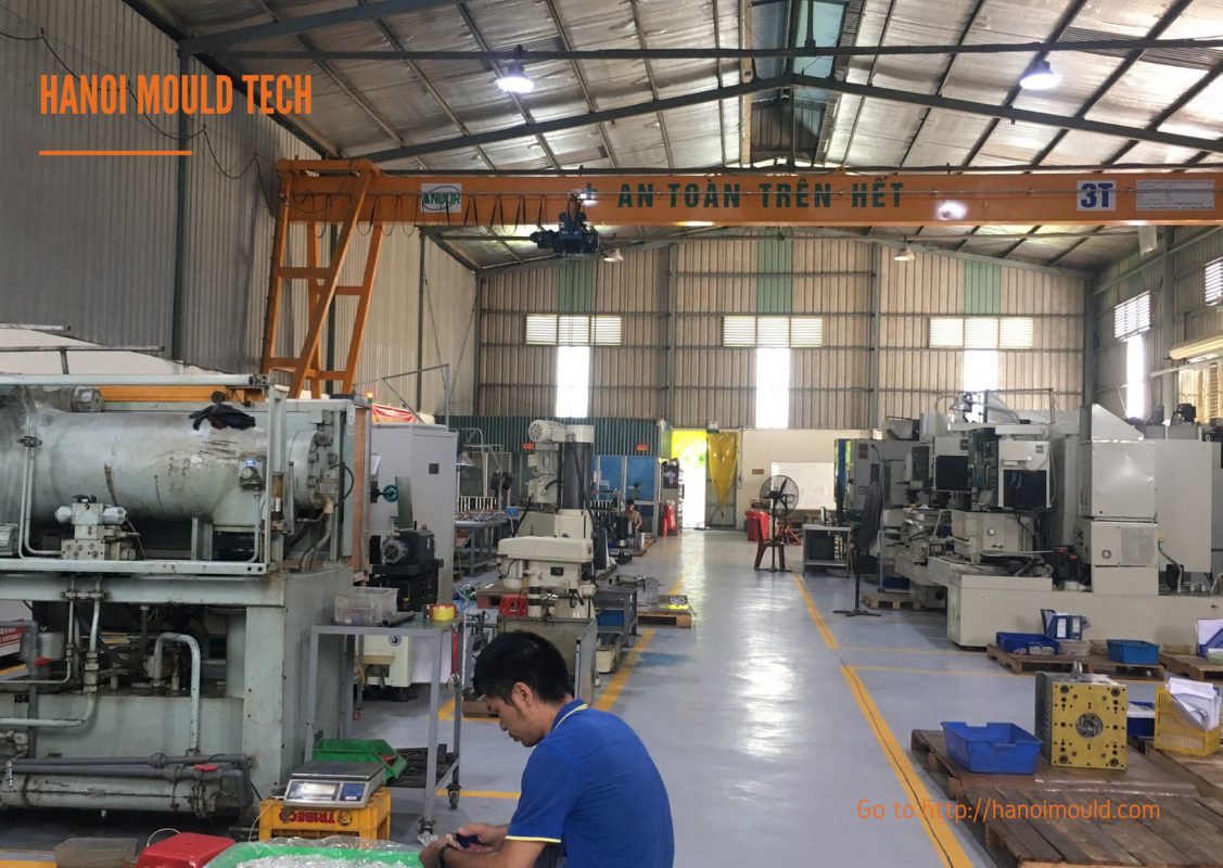
A stack mould places cavity groups on two or more moulding levels arranged along the opening direction of the injection moulding machine. It can increase the available cavity count within a given projected platen area, but it does not guarantee a fixed output or cost reduction. Feasibility depends on the part, resin, runner system, cooling, opening stroke, shot and plasticising capacity, clamp requirement, ejection and automation interface.
This guide explains the data and engineering checks needed before a stack mould concept can be compared with a conventional single-face, multi-cavity mould.
What is a stack mould?
A conventional mould normally has one primary moulding face. A stack mould adds one or more moulding levels around a centre section. Each level may contain one or more cavities, and the levels must work as one coordinated system during filling, cooling, opening and part removal.

The centre section may carry cavity inserts, runner components, cooling circuits and mechanisms for controlled opening. It requires stable support and guidance because loads are shared across multiple parting interfaces. The selected architecture must also match the receiving machine and the agreed part-removal method.
When should a stack mould be considered?
A stack mould is a project-specific option rather than a default solution. It may be worth reviewing when the buyer needs more cavities but wants to limit the projected platen area. A technical comparison should consider:
- part geometry, projected area, wall thickness and dimensional requirements;
- resin grade, shrinkage data, processing limits and hot-runner compatibility;
- required volume, cavity target and the approved production machine;
- shot and plasticising capacity, clamp requirement, opening stroke and tie-bar envelope;
- filling and pressure balance across every moulding level;
- cooling balance and access to water, electrical and control connections;
- part removal, robot access, conveyor arrangement and operator safety;
- tool investment, maintenance access, spare-part strategy and validation scope.
The comparison should not assume that twice the cavity count means twice the output. The cycle is controlled by the slowest filling, cooling, opening, ejection or handling condition. The receiving machine may also become the limiting factor.
Project and machine data required before design
| Input | Why it is needed |
|---|---|
| 3D part file and 2D drawing | Review geometry, projected area, draft, undercuts, critical dimensions and surface requirements. |
| Exact resin grade and TDS | Check shrinkage, thermal limits, pressure demand and runner suitability. |
| Volume and cavity target | Compare tool concepts and define the validation and maintenance scope. |
| Machine make and model | Confirm platen and tie-bar envelope, daylight, opening stroke, ejector arrangement, shot/plasticising capacity and available controls. |
| Runner and gate requirements | Assess filling balance, pressure loss, gate vestige, material handling and temperature control. |
| Part-removal method | Coordinate opening sequence, ejection, robot access, conveyor direction and cycle interlocks. |
| Inspection and acceptance criteria | Define evidence for level-to-level consistency, samples, dimensions, appearance and function. |
Use the injection mould RFQ data checklist to organize the initial package. If the design is still open, the injection mould DFM checklist helps identify decisions that should be resolved before tool release.
Key DFM checks for a stack mould
Cavity and projected-area balance
The cavity arrangement affects clamp demand, mould size, runner length and the load carried by the centre section. Projected area must be reviewed for the actual parts and runner system. Cavity count should remain open until the intended machine has been checked.
Filling and pressure balance
Every level should receive a controlled and repeatable melt supply. Runner routing, nozzle selection, manifold layout, gate design and process settings are evaluated together. Simulation may support the review, but trial evidence is still needed to confirm behaviour on the selected machine and resin grade.
Thermal and cooling balance
Cooling circuits should be reviewed level by level, including the centre section. Unequal heat removal can create different shrinkage, dimensions or appearance between levels. The design should account for circuit routing, flow access, connectors, temperature-control zones, maintenance and leakage checks.
Support, guidance and services
The centre section must stay guided throughout opening and closing. Support components, wear surfaces, locks, cabling, hoses and hot-runner connections should be arranged so that movement does not damage or pinch them. The maintenance team also needs safe access to the agreed service points.
Opening sequence and ejection
A stack mould uses a controlled opening sequence so that each moulding level reaches the required separation before part removal. The mechanism may be mechanical, hydraulic or another approved arrangement. Selection depends on stroke, load, timing, reliability, maintenance and the receiving machine.
Ejection must be coordinated with the opening sequence and the removal method. Pins, sleeves, stripper elements, air assist or other features are selected from the part geometry and acceptance criteria. Return confirmation and collision prevention should be included in the design review.
For related checks, see the mould design and manufacturing process and the mould inspection and validation page.
Runner selection is project-dependent
Hot-runner and cold-runner concepts should be compared against the resin, part, gate requirement, material-loss policy, temperature-control needs, maintenance capability and commercial scope. A cold runner does not automatically mean poor part quality or prevent automation. A hot runner does not automatically guarantee balanced filling. Both concepts require an appropriate design and validation plan.
The final choice should document the agreed components, control zones, connectors, start-up and maintenance requirements, together with the evidence expected during trials.
Trial and validation evidence
Trial approval should be based on agreed project criteria rather than a general statement that the mould runs successfully. Useful evidence may include:
- filling behaviour and part-weight comparison by cavity and moulding level;
- critical dimensions, appearance and functional checks from the agreed sample plan;
- temperature and cooling balance observations;
- opening, return, ejection and part-removal sequence;
- hot-runner, sensor and interlock operation where included;
- correction records and the status of open issues before shipment or the next trial.
Review the related plastic injection mould quality-control scope and equipment and production-capability information when preparing the project plan.
Frequently asked questions
Does a stack mould always double production?
No. It can add moulding levels and cavities, but actual output depends on cycle time, machine capacity, filling and cooling balance, opening/ejection sequence and part handling.
Can a stack mould run on an existing machine?
Only after the exact machine is checked. The review should cover the platen and tie-bar envelope, opening stroke, daylight, clamp requirement, shot and plasticising capacity, ejector arrangement, utilities and controls.
Is a hot runner mandatory?
No universal runner choice applies to every stack mould. The decision depends on resin, part geometry, runner balance, gate requirements, controls, maintenance and the approved project economics.
Request a technical review
HA NOI MOULD TECHNOLOGY COMPANY LIMITED (HANOI MOULD) begins a stack-mould review from the customer’s part data, resin grade, volume, machine information and acceptance criteria. The review identifies open technical points before a tooling concept or quotation is confirmed.
Send your project data for an engineering review and quotation.


